Choose the language.
TKART magazine Tech Talk | 2-stroke engine vs Wankel: a challenge of mechanics and efficiency
Exclusive Content

2T ENGINE vs WANKEL: A CHALLENGE OF MECHANICS AND EFFICIENCY

TKART Staff
01 August 2018
alt
Since the invention of the combustion engine, the winning mechanism has been the connecting rod-crank mechanism. However, other solutions have been tried over time, such as rotary engines and, in particular, the Wankel, also used in karting. A fascinating mechanical challenge that is worth telling
alt
alt
Advertisement
Almost all combustion engines on the market work thanks to a connecting rod-crank mechanism, whose motion is transmitted by one or more cylindrical pistons. It is a system that, thanks to its construction simplicity and reliability, has remained substantially unchanged since the invention of the combustion engine (second half of the nineteenth century) to date. In particular, the two-stroke engine dominated in karting, because of its simplicity, high specific power and low running costs. However, (the same goes for the 4-stroke engine), the connecting rod-crank system also has some disadvantages, such as the presence of high inertial forces generated in the alternating rectilinear motion of the piston, with a consequent loss in power due to friction. Thus, various ideas were
formulated over time to replace the alternating motion with a direct rotary motion, excluding the damaging dead spots of the piston inversion.
The rotating engine par excellence is the Wankel engine, invented by the German Felix Wankel in the first half of the twentieth century. The first Wankel engines were developed and produced by the German carmaker NSU, but several technological problems undermined its success. Subsequently it was Mazda who carried on its development, eventually market models of cars with an aspirated engine and a turbo.
On the other hand, other companies developed Wankel engines with contained displacements for specific sectors. For example, the karting sector, which saw the particular intervention of Italsistem.
The Wankel is a 4-stroke engine in which the rotation of a rotor, contained in a stator, puts the crankshaft in motion
alt
Simple diagram of the operation of a Wankel rotary engine
STATOR
alt
The stator is the "base" of the Wankel engine. Its shape is that of an epitrochoid, that is a bend generated by the rolling of a generating circumference on another fixed circumference
ROTOR
alt
An element that rotates inside the stator. It is shaped around the bends that surround an equilateral triangle, where all the points of the contour are equidistant from the opposite vertex
STEPS
alt
The 4 functioning phases of a Wankel engine: suction, compression, combustion with subsequent expansion, discharge
DISPLACEMENT
alt
The unit cylinder displacement is given by the difference between the two maximum and minimum values of the chamber. Without going into too much detail, the geometric equation is shown above: where S = thickness of the rotor; i = distance between the centre of the rotor and centre of the crankshaft; R = radius of the rotor (distance between the centre and the vertex)
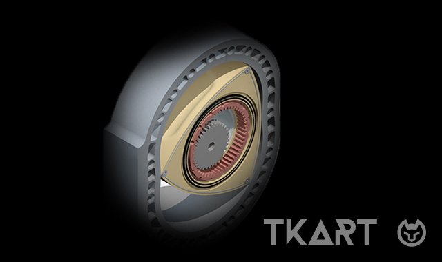
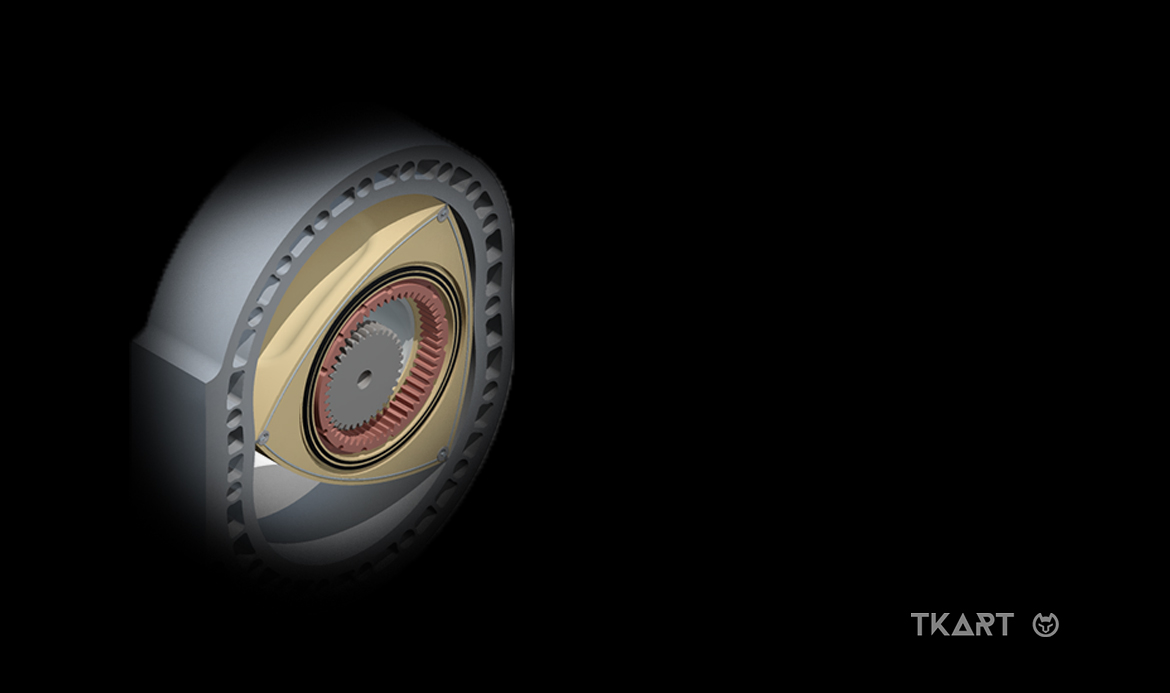
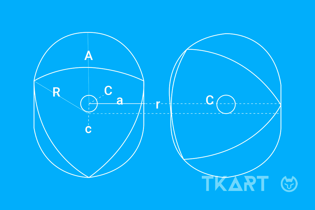
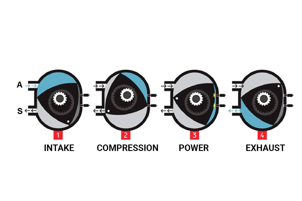
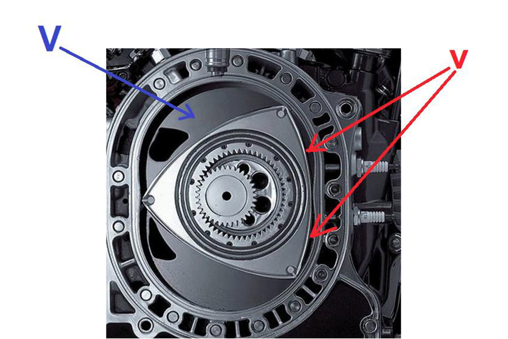
The Wankel is a 4-stroke engine which has one or more rotors that rotate and which, in turn, rotate a crankshaft, all contained in a stator, or a number of stators. The latter has a sort of epitrochoid-shaped base, and in the centre, on the side cover, a fixed gearwheel is fastened that acts on the internal teeth in the rotor, an element with three convex sides that acts as a "rotating piston". The gear ratio is 1.5: 1. At the centre of the rotor there is a large housing where a bushing is seated. An eccentric mechanism of a crankshaft rotates in the bushing which, together with the teeth, defines the motion of the rotor, ensuring that the three vertices with the relative seals always touch the stator’s surface, isolating three variable volume chambers. The eccentric shaft is supported by bushings mounted in the side covers. The thrust of the rotor on the eccentric, thanks to the shaft’s lever arm (i.e. to the eccentricity), generates the torque on the crankshaft.
Therefore, the Wankel engine is a 4-stroke engine whose 4 phases are comparable to those of a traditional piston engine, but with the peculiarity that the crankshaft (for a single-rotor) has a combustion phase at each revolution. On the other hand, the rotor performs 1 complete turn with respect to the centre every 3 rotations of the crankshaft. In other words: the rotor passes 3 times in the "spark plug zone" every 3 rotations of the crankshaft (therefore the 3 combustion phases are repeated). Result: a combustion for each turn of the crankshaft. As if it were a 2-stroke engine! The total displacement of the Wankel is obtained by comparison with a similar 4-stroke engine with traditional pistons. If, as we have said, the unit cylinder displacement completes a 4-phase cycle with every rotation of the crankshaft in a Wankel engine, comparing it with a traditional engine, the same thing happens in a 4-stroke twin cylinder engine with equal unit cylinder displacement (that is,
a combustion every turn of the engine shaft). Regarding equivalence, the total displacement of a Wankel corresponds to the unit cylinder displacement multiplied by two, in other words, in this case, as if it were a 4-stroke twin-cylinder. Or, by making a further comparison, as if it were a 2-stroke single-cylinder engine with the unit cylinder displacement. However, compared to traditional piston engines, the Wankel engine has very poor performance combustion chambers. This is the main reason why it is an engine that will hardly see future developments worthy of note. The shape of the combustion chamber in relation to its shape, is more or less squared (in part it is also obtained on the rotor), while we know that in an efficient chamber the ratio between the surface and volume of the chamber should be as low as possible (the top would be a spherical shape). This inefficiency leads to greater fuel consumption and, therefore, greater environmental pollution.
THE UNIT CYLINDER DISPLACEMENT IS GIVEN BY THE DIFFERENCE BETWEEN THE TWO VALUES OF MAXIMUM AND MINIMUM OF THE CHAMBER
alt
The picture shows the 3 variable volume combustion chambers
Continue reading the article by subscribing for only 0.96 € / week
1
Explore these and many other
premium contents
Go to Magazine