Choose the language.
TKART magazine How To | Reassembling an OK engine
Exclusive Content

REASSEMBLING AN OK ENGINE

TKART Staff
26 May 2016
alt
alt alt
Advertisement
1 INTRO
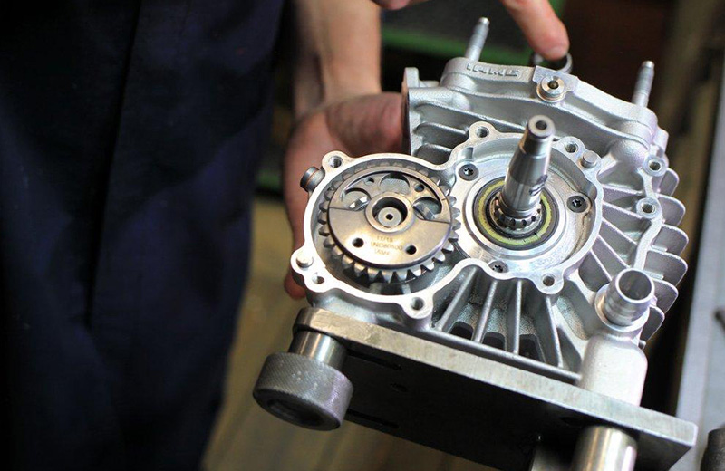
Reassembling an engine following an overhaul is not overly complicated. However, there are some expedients that can significantly alter both the reliability and, in some ways, the performance of an engine. With the help of an IAME specialist, let’s take a look at the steps and the "secrets" behind reassembling an OK engine.
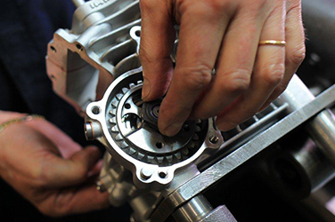
Once the engine has been and the parts in the crankcases have been replaced (main bearings, big end, gasket seal, etc.), the first step is to clean the contact surfaces of the two crankcases, removing the old gasket paste using a cloth and the blade of a utility knife. Then, put some nitro onto the load surfaces of the two crankcases and dry thoroughly with compressed air.
2 PAY ATTENTION TO THE GASKET SEAL
The next step is to insert the crankshaft in the crankcase, while holding firm the latter, if possible, using a specific tool. To prevent the sharp edge of the crankshaft from knocking against the gasket seal, thereby ruining it and allowing the spring to fall out, use a “protective” cylindrical sleeve.
Once the crankshaft has been inserted, put some grease (Molykote) between the two sealing lips of the gasket seal, so they do not run dry, and some oil on the main bearings.
3 JOINING THE CRANKCASES
Using your fingers, spread some red paste on one of the two crankcases (preferably on the side without rods). Join the crankcases, making sure that the crankshaft does not damage the gasket seal, and insert the locking bolts by initially tightening them slowly to let out the excess red paste, then tightening them using a torque wrench adjusted to 1.2 kg (in general, all 6 mm screws should be tightened to 1.2 kg). Tighten the screws in a criss-cross pattern, starting with the internal screws, followed by the external ones. Once the screws have been tightened, check that the crankshaft turns properly (freely).
4 BALANCING SHAFT
It passes the post balancing assembly, oil wetting in the two points of contact with the ball bearings that support it. This will facilitate the insertion which, however, can be helped with some slight blow given with the plastic hammer.
Once the post inserted occurs that is not blocked but has a minimum of longitudinal play.
5 TIMING ADJUSTMENT
To adjust the timing, the countershaft weight is positioned at the bottom, as is the weight of the gear wheel to be mounted on the countershaft. With the connecting rod ATDC (top dead centre, namely the maximum height of the piston in the cylinder), mount the gear wheel on the shaft, with the mark aligned to the marks on the shaft and the balancing shaft gear wheel. The engine will therefore have the correct timing. With the torque at 40 kg, tighten the nut on the countershaft wheel, add blue clamping screws (medium) and hold the shaft still using a special tool (cod. ATT008 IAME). The same should be done with the crankshaft nut, using 70 Kg of torque.
Continue reading the article by subscribing for only 0.96 € / week
2
Explore these and many other
premium contents
Go to Magazine