Choose the language.
TKART magazine How To | Kart accessories with 3D printer
Exclusive Content

KART ACCESSORIES WITH 3D PRINTER

Max Bernardi
26 July 2017
alt
alt alt
Advertisement
1 CONTINUOUS DEVELOPMENT
“Kart is a simple vehicle, for years we have maintained the same chassis shape”. This statement, frequent and somewhat over used, contains without a doubt, a kernel of truth. For years, in fact, almost all produced chassis have the frame’s classic design. This, though, does not mean that the kart has not improved in respect to the past. The only difference is not in the shape of the chassis as in the different types of tubes used and in the welding process. But the main sign of a development run that never stops, is much more evident in the accessories field: braking systems, stub axles, pedals, hubs…all parts of the chassis are in a continuous process of improvement. IPK, the company which manufactures the chassis for Praga, Formula K and OK1, is one of the most prolific companies in testing and offering new and improved accessories, and it is convinced that succeeding in producing prototypes in the least amount of time and without stopping the continuous production is a fundamental factor. For this reason, it has worked relentlessly on the introduction of the 3D printer. TKART went and saw how it works.
alt
alt
2 3D PLANNING AND DESIGN
Everything starts with a design. This is the first step to make the ideas of the technical team solid, on one side, and on the other side the requests of the racing teams technical manager. All suggestions are attentively evaluated and taken into consideration to execute it on the CAD design computer, ensuring the part is properly made. It is one of the most important phases, in which, depending on the accessory, the possible materials, the thicknesses, the strength, the functionality and the visual aesthetics are studied. The 3D design obtained is the representation on the monitor of the piece to be produced, with the right dimensions and all the characteristics of the finished product. With this, the technician can further reason and evaluate other possible changes in comparison to the original idea.
alt
3 PRINTER LANGUAGE
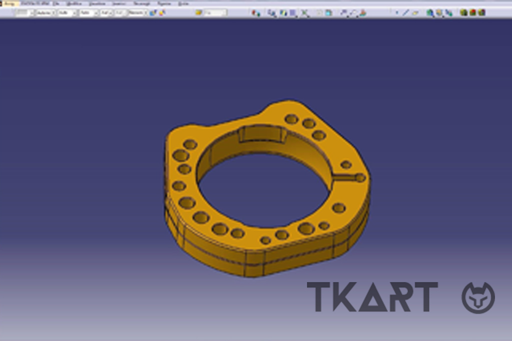
Once the design has been executed on the computer, it is exported to the reading format of the CAM program, specific for the 3D printer. When the information has been imported, it is necessary to set the parameters to prepare the language necessary for the printer in order for the element to be implemented. The fundamental parameters are:

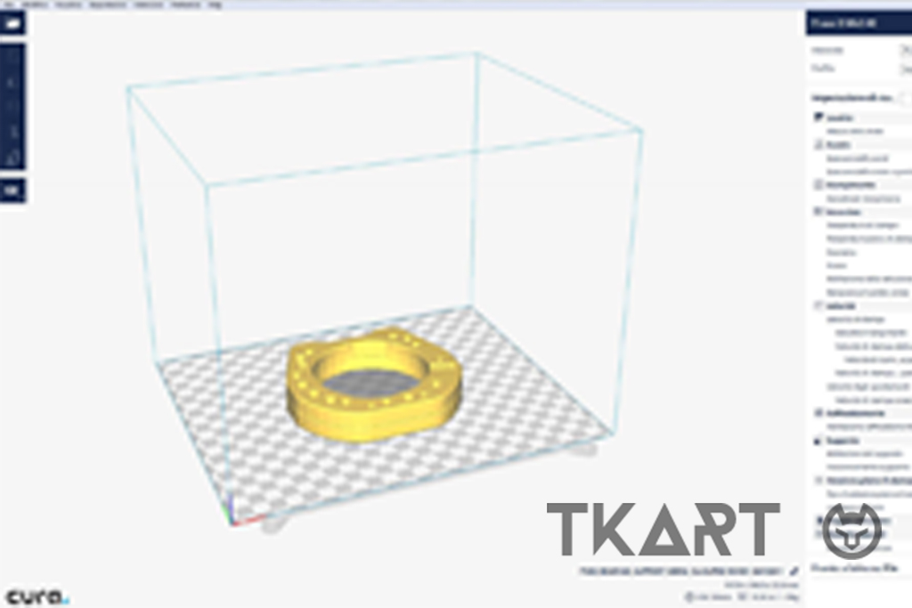
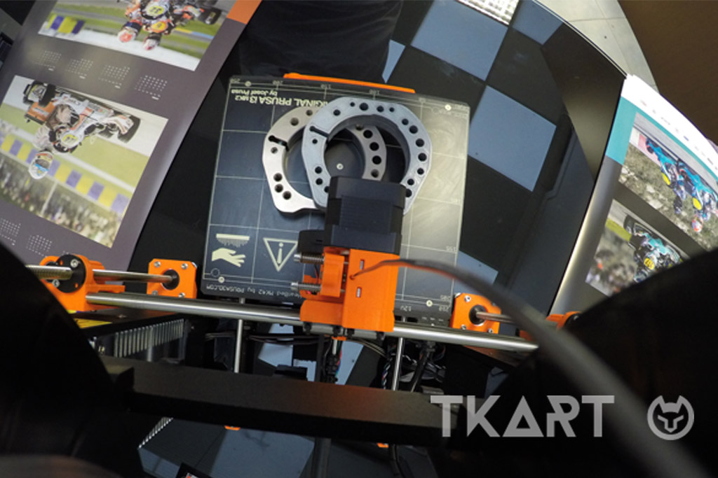
POSITIONING: the position of the piece in comparison to the plane of the machine is important. If the dimensions allow for it, in fact, several pieces can be created simultaneously (for example, the brake pads). The side that needs more processing is placed facing upwards to obtain a better definition.

QUALITY: it depends, simplifying, from the “quantity” of the plastic used. The value of the plastic layer thickness is set on the Z axis, which the machine will release to shape the piece: to achieve a high definition, it is possible to execute steps of 5 hundredths. The more the values increase (up to 1,2 tenths), less time will be necessary to achieve the piece, but also its quality as well.
Another influential factor is the filling, that is the parameter which defines percentage wise, how much material to insert inside the object that is being created. If only the aesthetics is of interest and not the solidity, a low value can be inputted. The higher the value, the better the quality but also the time necessary to obtain the piece.

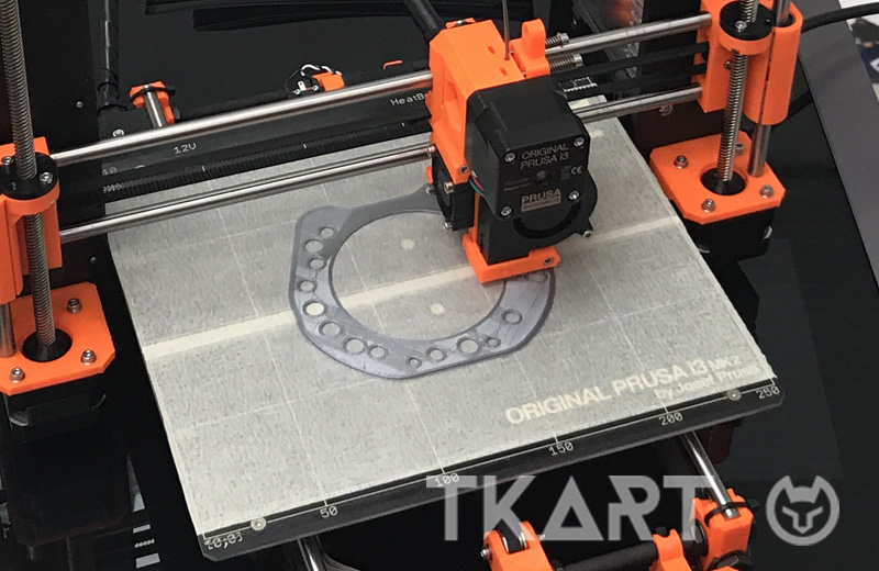
ADHESION TO THE PRINTING BED: there are various basic types on which to print. Usually, the machine bed is covered with masking tape to avoid damaging it. The adhesive tape also improves the grip of the piece to the bed. Definition is improved if a glass sheet is used, laying it on the printer bed, thanks to the smoother surface on which the material is placed.
alt
4 EXPORT AND PREPARATION
When all parameters are set, on their basis and that of the piece being produced, the program supplies the necessary data relative to the duration of the printing and the material needed for the production. In the case of the bearing used for this item, 19 meters of wire and 6 hours of time are necessary, for a prototype which the final weight will be 58 grams.
At this point, the computer work is completed. What is left to be done is to export the file to obtain the G-code (a code telling the machine tool what type of action to perform) to be inputted or sent to the printer to begin the actual printing. Not before, though, having carefully cleaned the printer bed and applying the masking tape.
alt
Continue reading the article by subscribing for only 0.96 € / week
1
Explore these and many other
premium contents
Go to Magazine